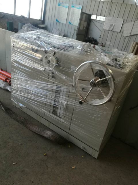
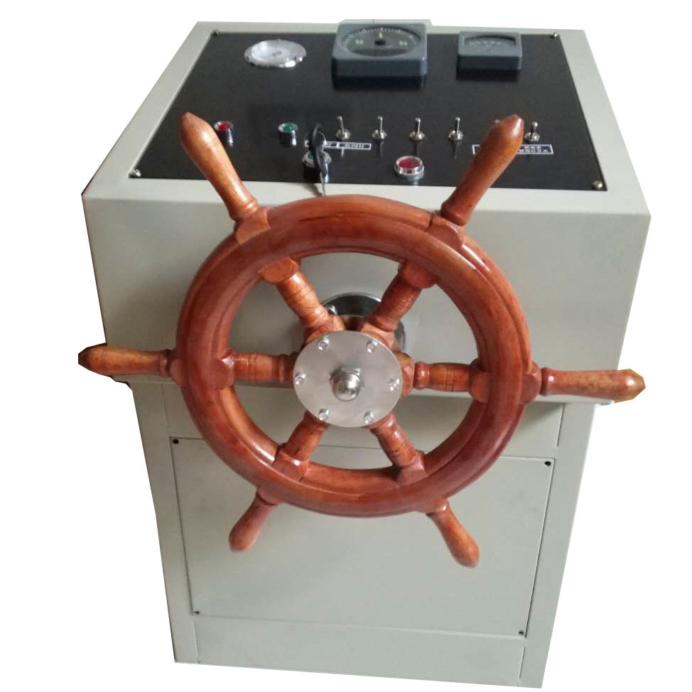
The steering system in accordance with the《Rules for classification of ships》on the steering gear in the requirements for the design, the use of open-type valve hydraulic system and swing cylinder piston to push the rudder mechanism, with avariety of valve type (such as HD-S type) or autopilot servo steering instrument to match the ship's steering control system components, and undertake the task of changing and maintaining the course of the ship.
The full rudder servo transfer time ≤ 28S (sea-going ships).
The steering gear has two completely independent pump motor unit can be used in rotation (also mutual backup)
Main Specifications
| Name | Sino-Winch-24 | |
| 1 | Rudder Machine Mode | SINO-W125-30 |
| 2 | Nominal torque | 30KN.m |
| 3 | Turn the wheel full time | ≤28S |
| 4 | Maximum steering angle | ±35° |
| 5 | Mechanical limit angle | ±36.5° |
| 6 | Steering radius | 270mm |
| 7 | Working pressure | 8.5MPa |
| 8 | relief pressure | 10.6MPa |
| 9 | Pump Model | 25SCY14-1B |
| 10 | AC motor model | Y132S-6-H(3kw) |
|
The steering gear is characterized by: pushing the rudder mechanism adopts swing cylinder piston, simple compact structure, light weight, easy installation process, valve assembly, integration and a high degree of hydraulic components are domestic famous brand, reliable quality, replacement convenient, hydraulic system uses the open system, the hydraulic system simplified. In addition, the possible failure of the site, located a sound and light alarm devices, thereby improving steering vitality. |
 |
 |
 |
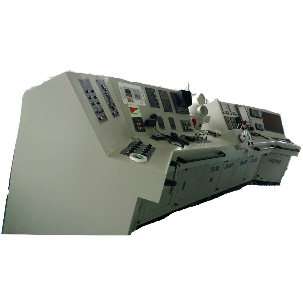
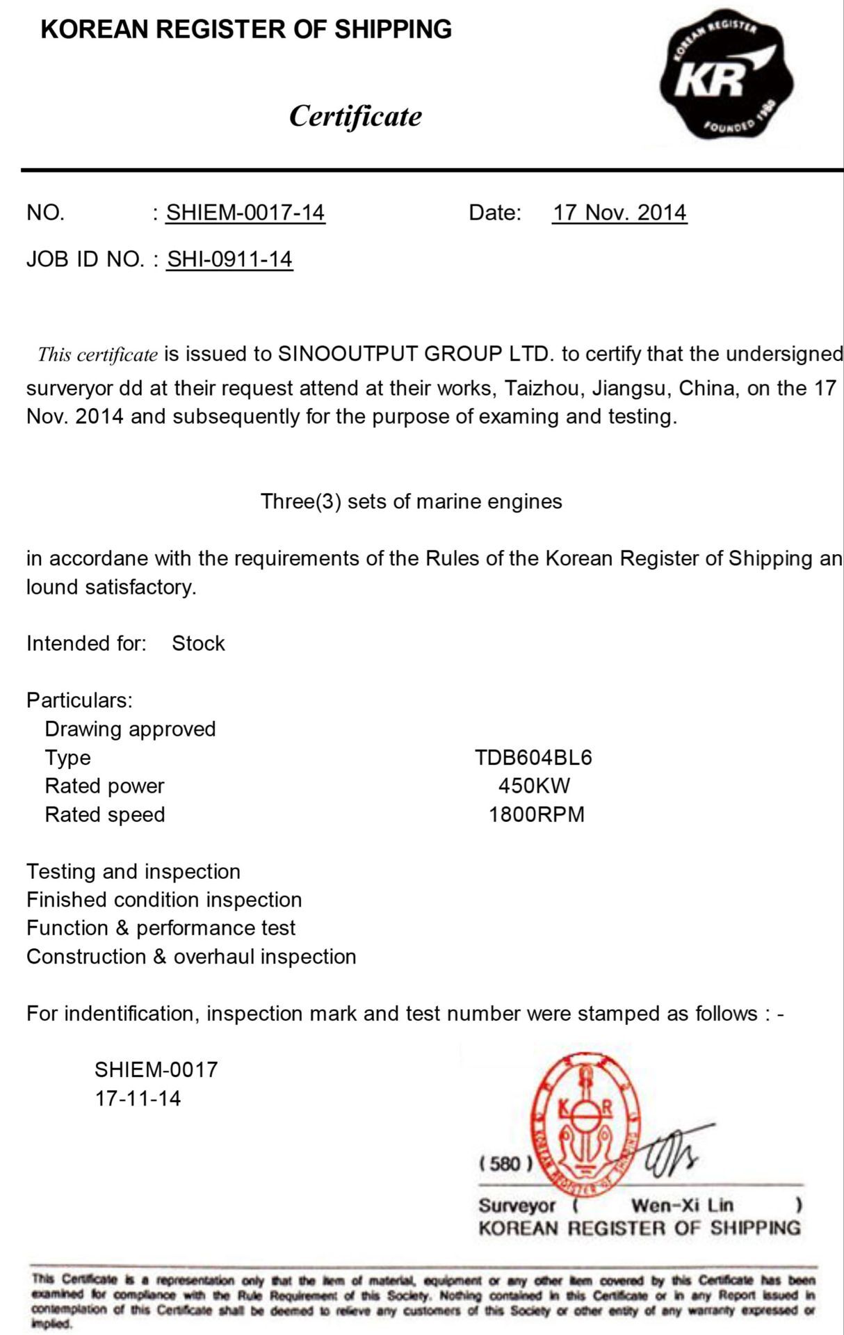
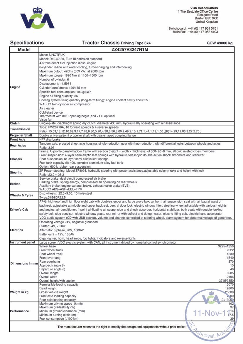
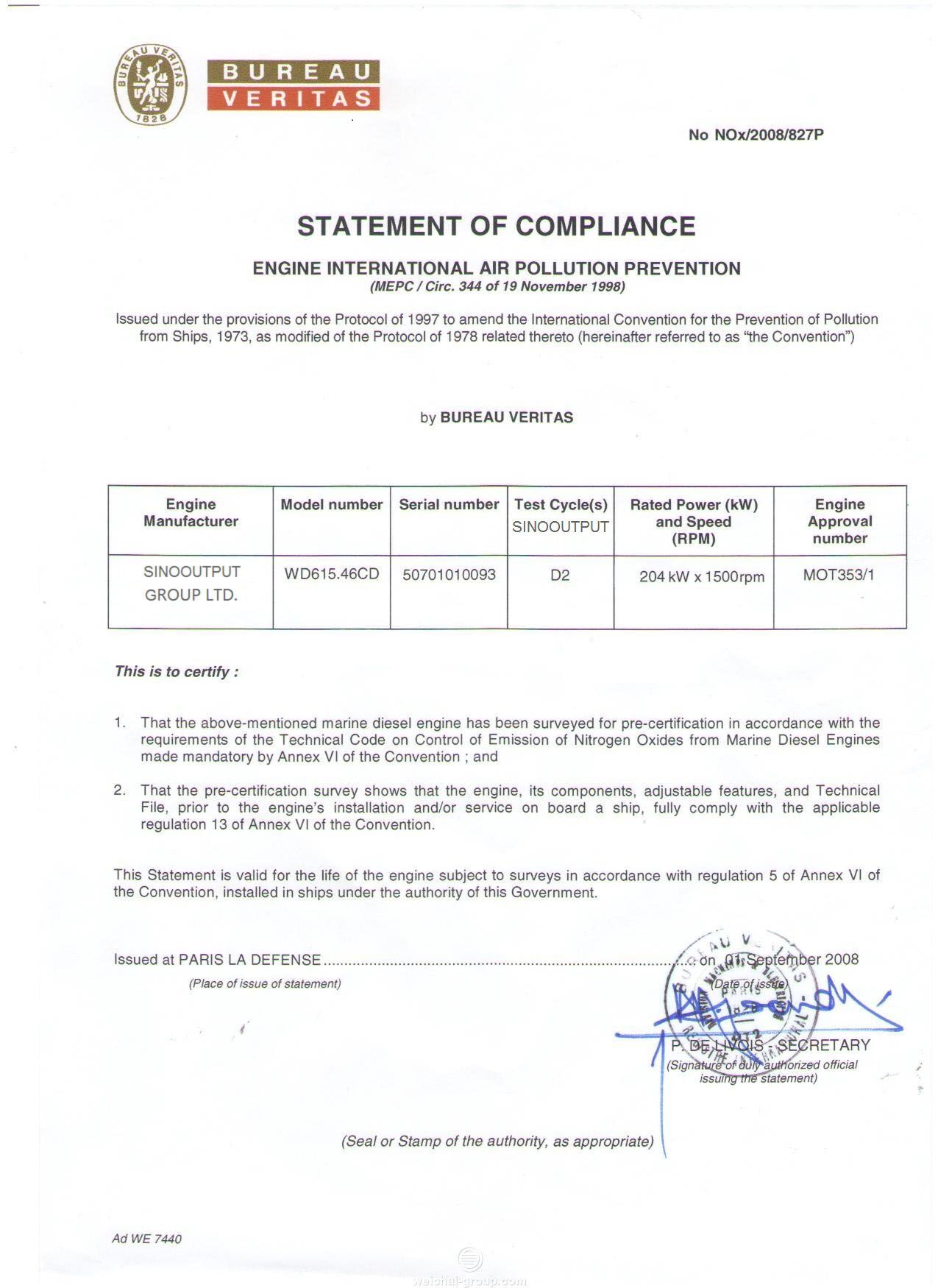
Certifications
 |
 |
 |
 |
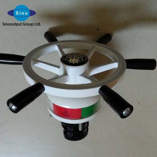
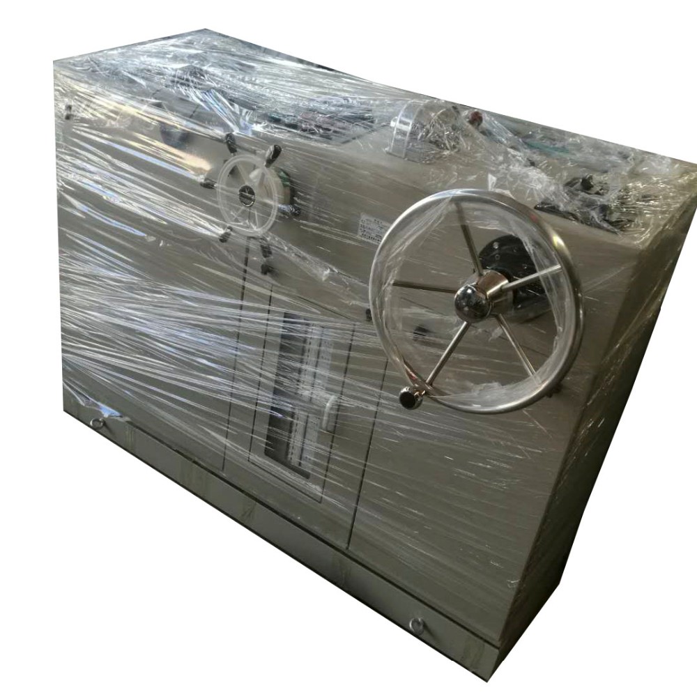
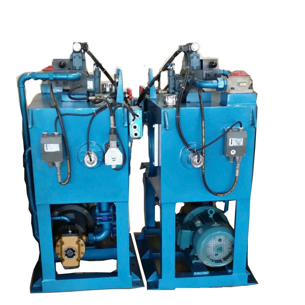
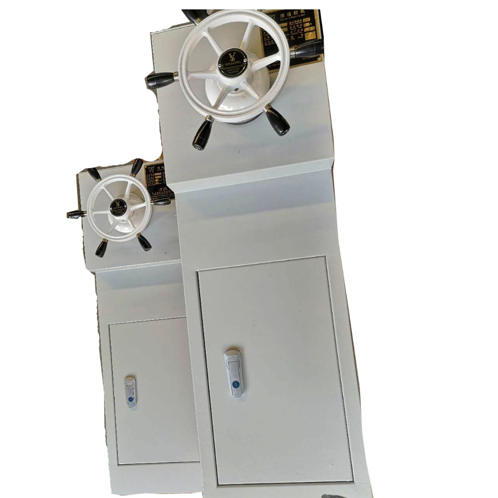
Detailed Images
 |
 |
 |
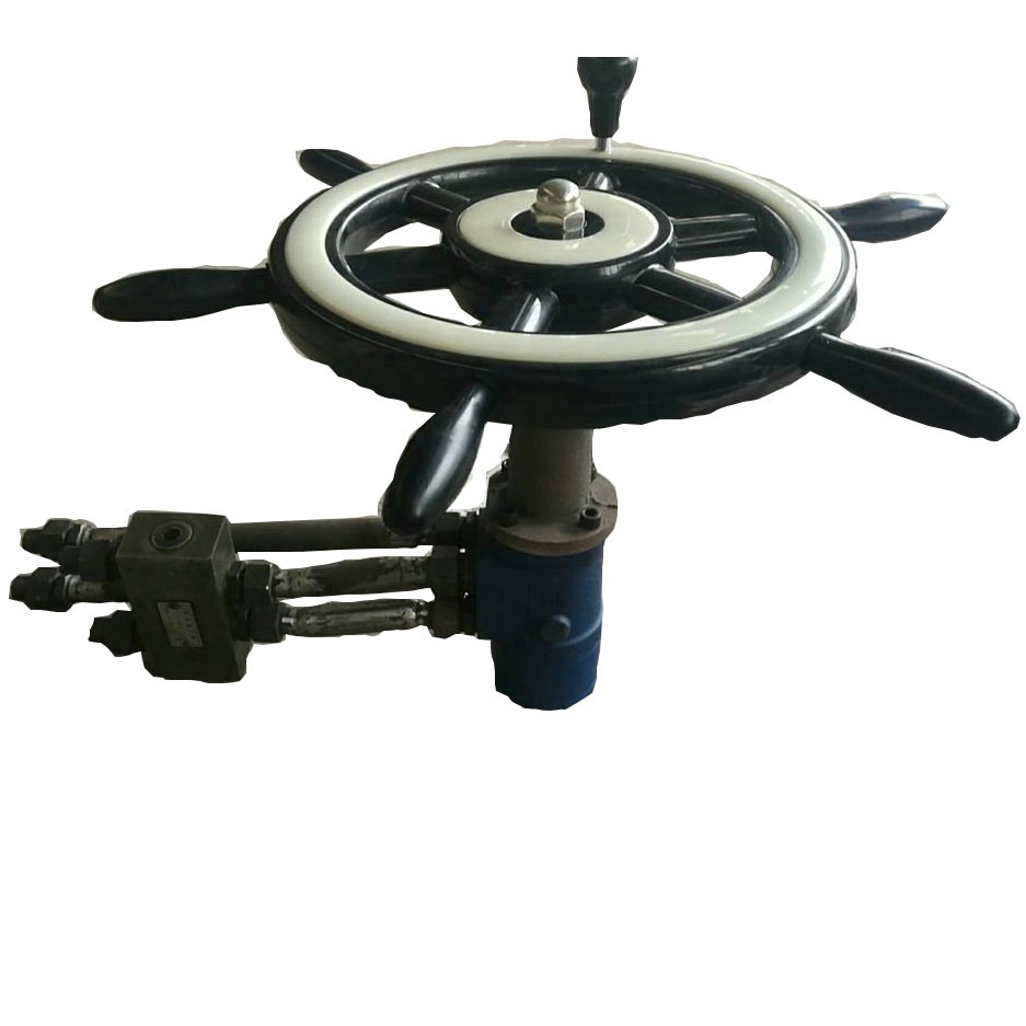
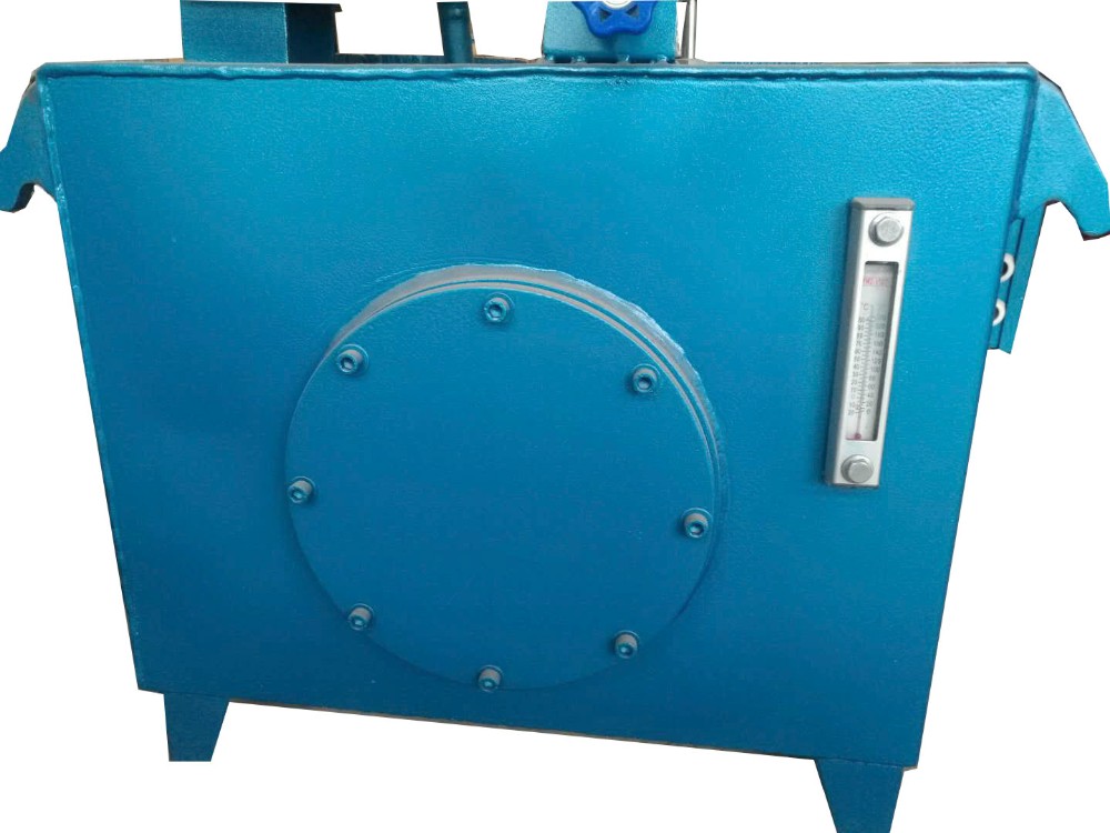
The rudder mechanism is a mechanism that converts the hydraulic energy produced by the oil pump into mechanical energy,It is composed of an oil cylinder, a piston, a base, Px type shaft sealing ring, O ring, ring etc.
Oil cylinder is a pressure vessel with thick wall seamless steel pipe welding, it is also an important component of thrust to the hull.
Pistons are made from forged steel cylindrical parts, which fit with the cylinder to form the pressure vessel work together to complete the conversion of energy, it directly through the thrust generated by the hydraulic piston pin slider passed rudder tiller, the rudder blade rotation.
The piston and the cylinder are sealed by three Px type shaft sealing ring, O ring and dust ring.Seal assembly loose or tight can be adjusted by end cap screw.
On the top of the cylinder is also provided with a double stop valve, under normal circumstances, the double stop valve should be fully open, if necessary, just turn off the part or all of them(for example: in the normal navigation, without the need to dismantle the inspection of a pump motor group, the other pump group continue to use to ensure the independence of the two pump turbine).
In addition to the steering gear is equipped with an electrical limit device, there is a mechanical limit device, that is, by the end of the piston to go to the limit, the bottom of the cylinder can be achieved mechanical limit, the rudder angle is ±36.5 degrees.
 |
 |
 |
|
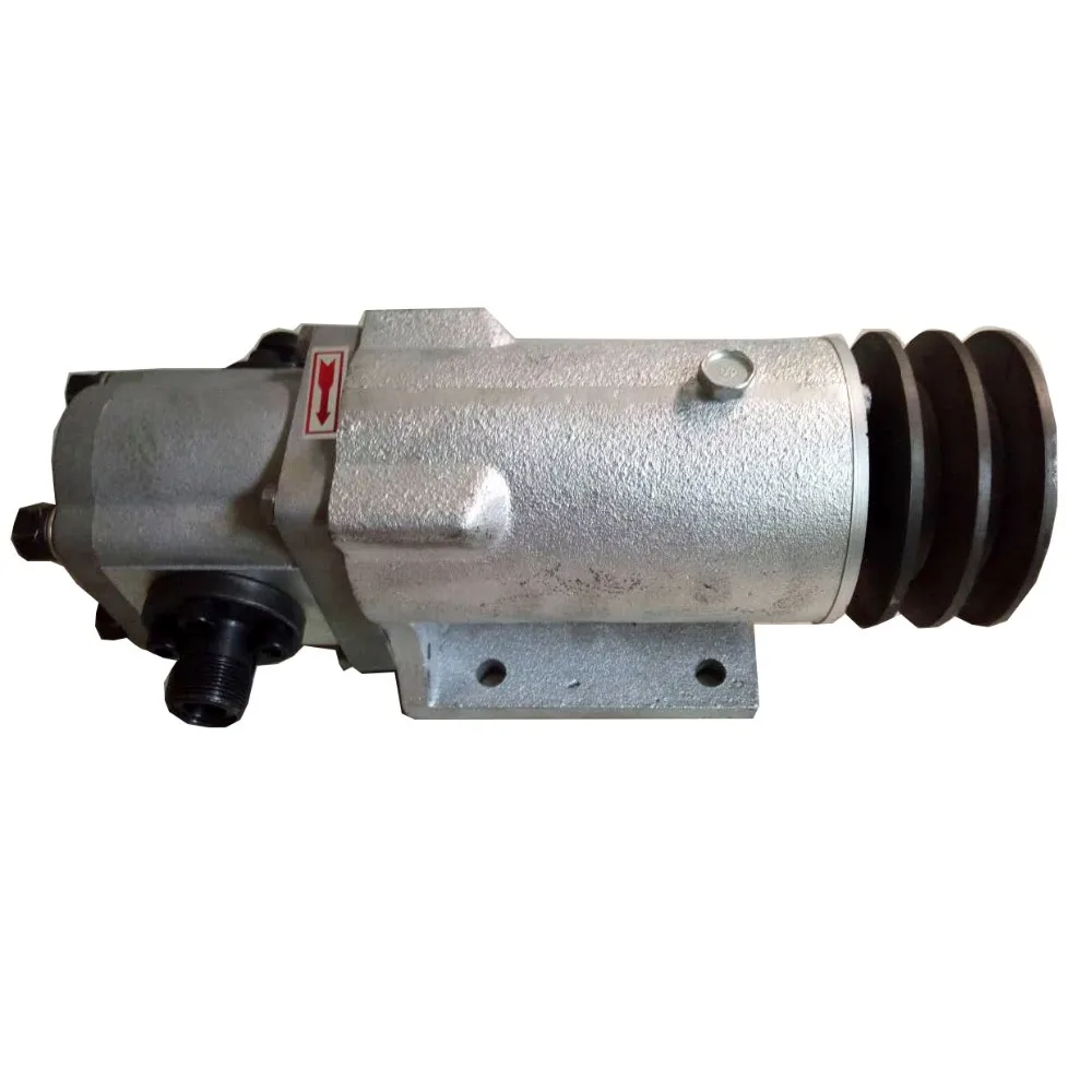
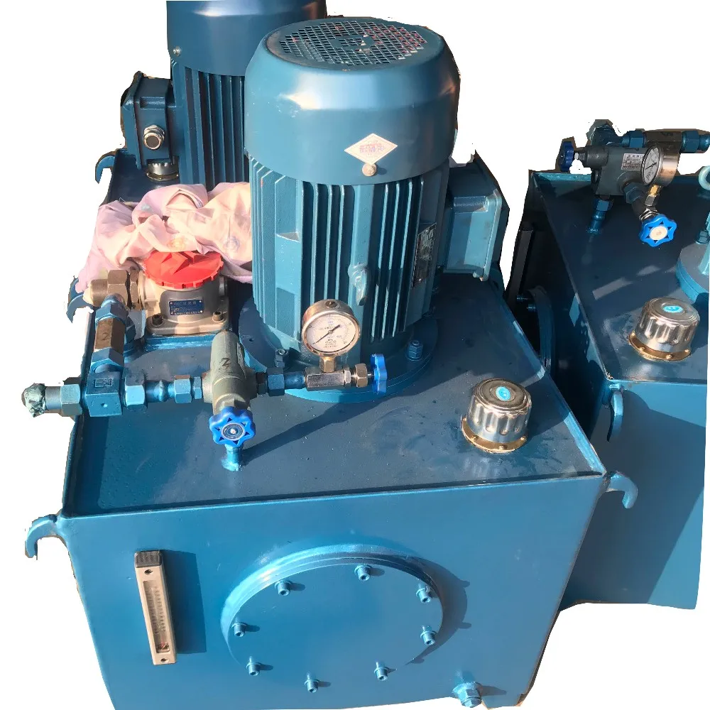
Oil pump motor group is the power source of the entire steering engine, it consists of two sets of left and right units, each unit consists of a marine motor, a matching pump, a variety of valves, Various valves,piping and other components. |
Reserve tank and its purpose is to give daily hydraulic tank due to leakage caused by the hydraulic system when the complement of the oil level is too low to use, designed and manufactured by the user. | Hydraulic control system comprises the high-pressure relief valve, solenoid valve, special valve (two-way balancing valve, safety bypass valve combination), low-level alarm device hydraulic, filter clogging mouth, loss of pressure alarms. Pressure relief valve is to protect the pump from overload effect. |

Below to the right side of an oil pump motor group as an example to illustrate the work of the
steering gear,when the oil pump motor group is started,solenoid (liquid) valve in the middle of the
center position and remain on standby,At this point, oil pump oil from the oil tank,the rudder
cylinder is in a closed state,the rudder is fixed to a certain angle.If the ship needs to turn or turn
around, the operation of electromagnetic (liquid)valve can reach the purpose.the solenoid valve is
reset to the middle position at this time,the rudder angle is locked in a fixed position.
1, The hydraulic steering gear is installed in the hydraulic system diagram and installation sketch map
2, System piping should refer to the hydraulic system combined with site conditions map and
reasonable layout, using Φ22 × 4 high pressure seamless steel pipe, low pressure pipe used φ25 × 3
seamless steel pipe; seamless steel pipe should be thoroughly cleaned before installation, pipe wall
can not have any impurities (such as scale, weld, oil, rust, etc.);
3, The base plate of the push rudder oil cylinder should be flat, and the steering cylinder is fixed well according
to the schematic diagram of the installation, and the limit block is welded on the bottom plate to bear the axial
force and lateral force;
4, After installation, the system should carry out the pressure test, the test pressure is 1.5 times the working pressure,
which lasted for 5 minutes, no leakage and permanent deformation;
5, Circuit laying is implemented in accordance with the electrical principle diagram, ensure